Summary:
This blog post details how to import solid bodies into Blender from NX. As always there are many different ways to skin a cat, but I was only able to find particular combination of files types and tools to maintain solid body definition after the import into Blender. The assembly model I wanted to import from NX had over 50 different bodies and over 500 surfaces. Even trying to select all of the surfaces associated with a body and creating a group or linking them would be impossibly tedious and wasteful. Hopefully this information will save you time and effort as well!
Steps:
I'm going to use this part with two bodies, a cube with a square cutout and a cylinder, as an example and walk through the process.

1. Export the model from NX. I'm using NX7.5. File -> Export -> Parasolid

2. A new Export Parasolid dialog will pop up. Select the desired bodies to export or Ctrl+A for all bodies. The desired bodies should be highlighted and the OK button should become green/selectable. Click OK.

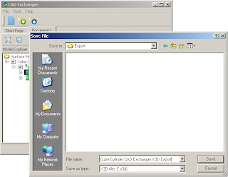
3. Browse to the desired output directory and name the output file.

4. Download and install CAD Exchanger. Unfortunately this is not freeware or open source, but there is a free trial period (no idea the duration) and it was the only file converting utility I could find that could go from parasolid to x3d.
5. Open CAD Exchanger. Before we get started we need to enable "Merge Face Sets" in the X3D exporter options. Go to Tools -> Options. Click on "X3D exporter" in the left hand list. Check "Merge Face Sets". Click OK.

6. Start a new file, File -> New.
7. Import the recently exported parasolid file, File -> Import.

8. You can see a preview of the model and solid bodies in the tree to the left.

9. Export the model, File -> Export. Select X3D files (*.x3d) in the dropdown menu). Name and save the file.

10. Open a new file in Blender and delete the auto-generated cube. Your screen should look something like this. I'm using Blender 2.68.

11. Import the newly exported X3D file using File -> Import -> X3D Extensible 3D (.x3d/.wrl).

12. Browse to the X3D file, select it, and click "Import X3D/VRML2".

13. After rotating and scaling this is our cube and cylinder! Done!

Hope someone finds this helpful, I know it would have saved me quite a few hours of trial and error. Please post successful results or questions in the comments as well as if you find a free/open source file converter.